![]()
![]()
![]()
![]()
![]()
![]()
![]()
![]()
|
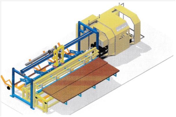
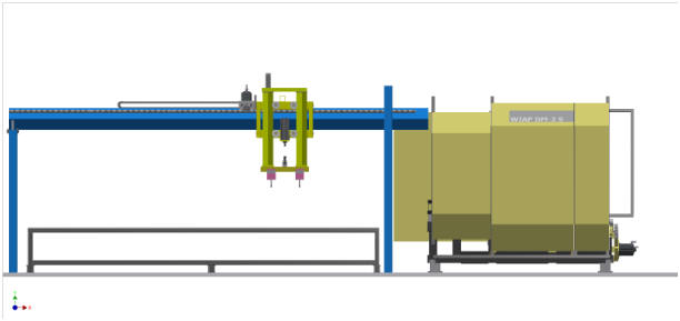
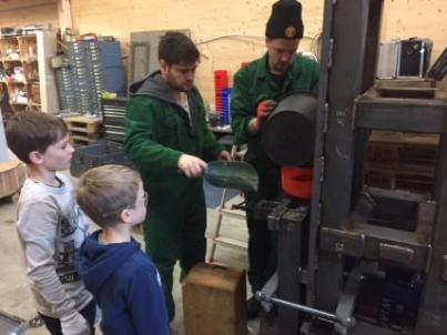
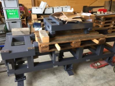
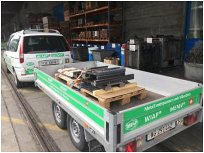
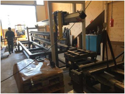
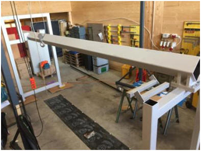
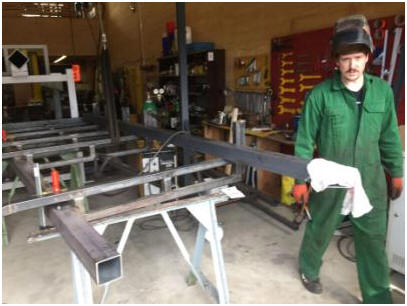
CNC-controlled multifunction machine WIAP DM3S for processing rebar
Robust heavy construction. 70x40 guide, ball screw robust.
Simultaneous spindle head and roller burnishing head, instead of burnishing head prepared for facing head
Machine bed prepared by the method WIAP VDSF; 1250 kg MEMV relaxed and vibration dampened filled
Automation in the preliminary phase
Double gripper WIAP HLV 40 for 40 kg unit weight
Blank feeding and carrying away the finished part diameter to 40 mm in length up to 4100 mm
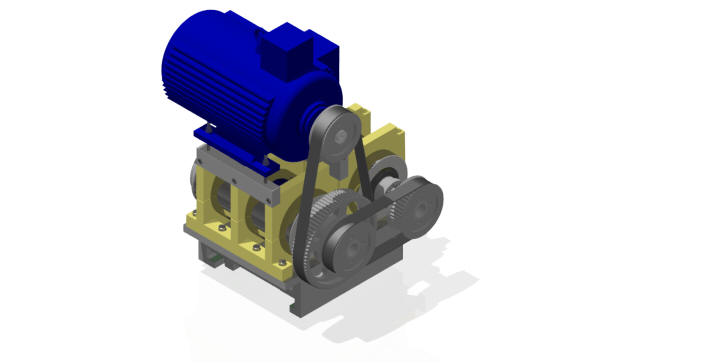
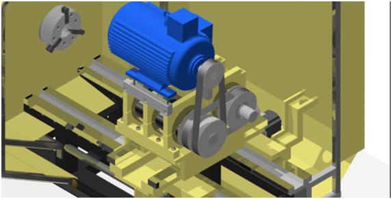
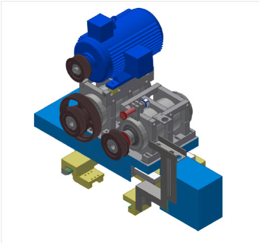
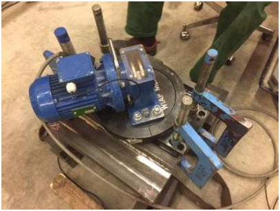
Rolling head
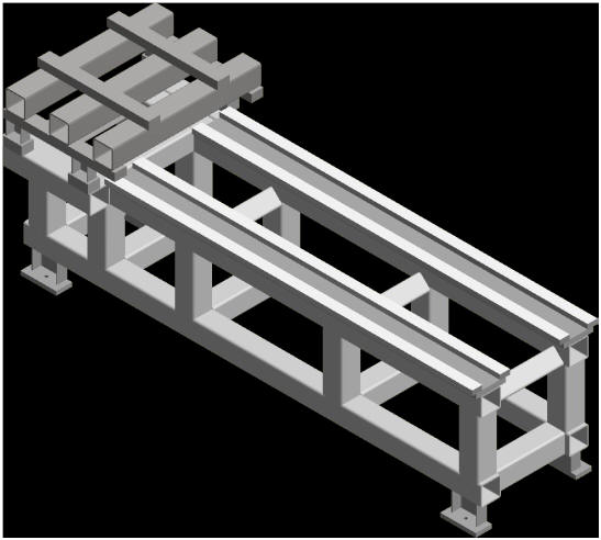
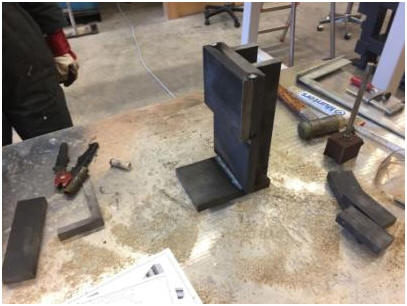
Assembly 1 machine bed DM3S; MEMV relaxed, vibration dampened
Photo 10
Photo 12
Photo 14
Photo 16
Photo 18
Photo 20
Photo 22
Photo 24
Photo 26
Photo 28
Photo 30
Photo 32
Photo 34: Bed return delivery with console
Photo 36: Bed with headstock console
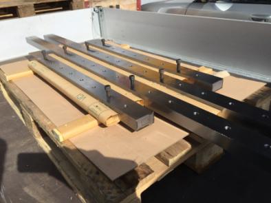
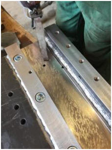
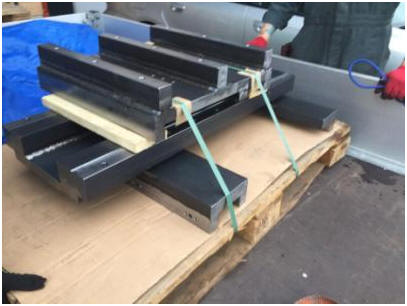
Assembly 10 Guides
Photo 50
Photo 52
Photo 54
Photo 38: Scraper specially made for WIAP 40x70 purchased for 3 machines in stock
Buy scrapers for 3 more machines
Assembly 5 headstock on cross slide
Photo 56
Photo 60
Photo 62
Photo 64
Photo 66
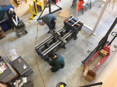
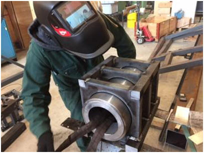
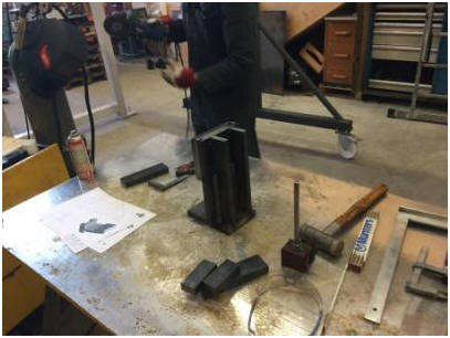
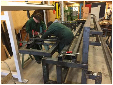
Welding spindle in burning plates
Jim and Sven
Headstock in WIAP Welding
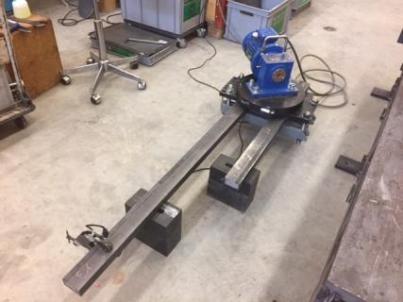
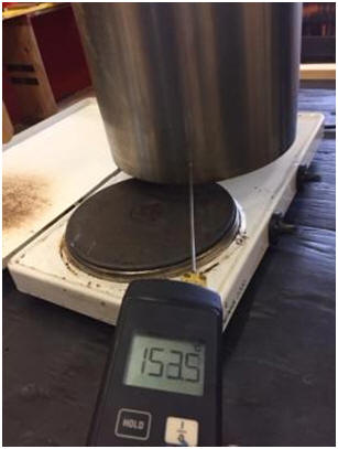
3 directions MEMV stress relief. Logging of relaxation of both headstocks
Jim by the G measure for the MEMV Protocol
Sven by MEMV data rapport
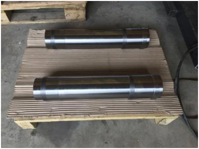
2 headstocks DM3S from the processing back
Headstocks still plastered before painting, Linus third generation, has school holidays and exercise manual skill.
Paint priming and 2 K
Assembly 03 Z carriage
Photo 80
Photo 82
Photo 84
Photo 86: Here, the Z slide is in MEMV 4 axes direction axial directions vibration-relieved
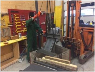
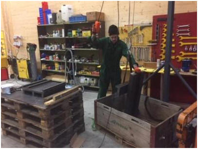
Here we get the slides back from processing.
Mounting preflight whether the mass are also ok.
|
|
Now comes the whole lubrication make the system
Per slide lining there are two lubrication points with single feed above the third that is, a carriage has oil allocations above 4 for the lower grips and 4 for the front and rear total = 14 oil allocations per axis, i.e., the x 2 nor for the X
Drill several hundred mm lubrication channels that admission is only on one side per lane
Be milled sliding coating test with lubrication paths before
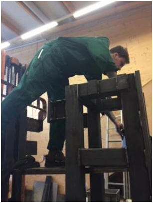
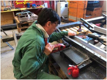
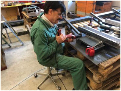
150 mm deep drilling for lubrication
Deep hole drilling with hand machine
That takes strength as deep drilling and make an effort, that the drill does not break off.
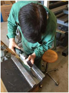
The sliding coating bearing surface scrape, that adhesive has better engagement
surface
Under handles are milled in the height adjusted that the 2 mm plastic also has its place. Taken into account that grows differently at higher temperatures than steel
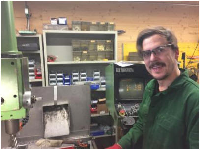
Jim CNC specialist. Much he makes himself with the Mikron CNC milling machine
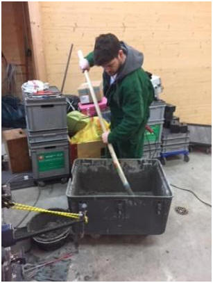
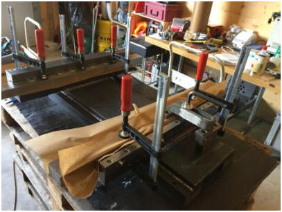
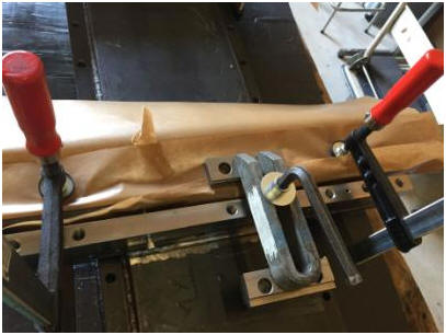
Sliding coatings stick a specialty. Mixing ratio of glue to hardener 1/4
The Z slide is made first, the X can then dry ending Z is scraped.
A good press down the strip that the adhesive is displaced is important.
Z slide nut mount in the welding
Robust design that it does not move.
Assembly 04 X carriage
Photo 88: Even the X carriage we covered in 4 axis directions MEMV
Delivery of the X carriage
Many M8x1 for the lubrication connections. On the X slide
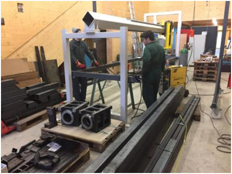
Assembly 20 HLV auxiliary charging device
Photo 250
Photo 252
Photo 254
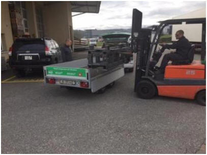
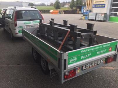
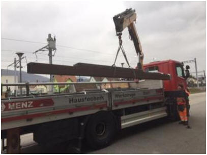
Delivery of steel for automation ca. 2 tons.
Welding beginning of the HLV to and carrying away
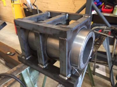
Frame welding
HLV frame (HLV = auxiliary charging device)
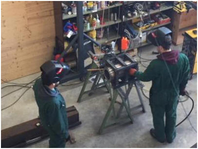
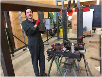
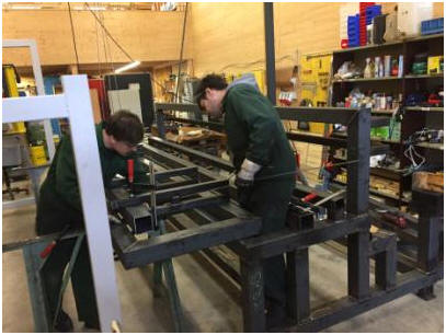
Sven strives for every mm. Everything must be perfect just
Jim and Sven during welding, which is almost not alone
Soon the HLV is frame ready.
The place is already scarce anyway it comes.
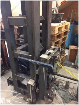
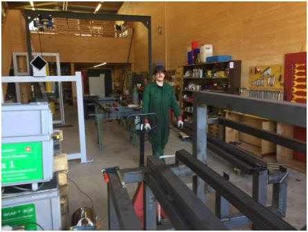
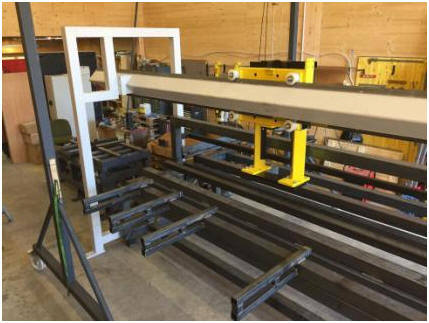
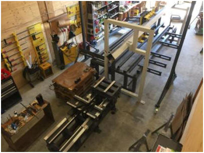
View from the basic framework of the plant.
Workpiece depositing sliding webs.
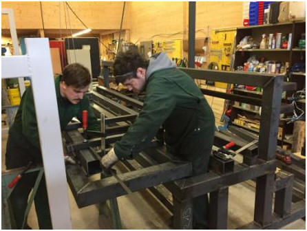
Jim and Kim, the grandson has school holidays wants to help.
Kim weld on, he was proud that he could. Thanks to the automatic helmets not as hard as before.
He plastered. Also, he does well. Think he will get the same profession as his two uncles and the mother.
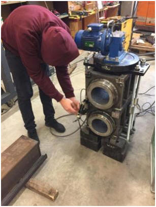
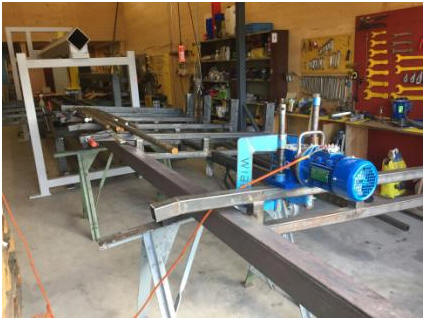
Vibration test whether the material handling works as planned on paper. Depending on the response, the rods can be transported in place even down to the top. But it can obliquely, we still need an additional separation build that they only just can in the rotary claw 1.
So now the steel has come for the hinges of automation. Which can now be done soon. Once that is on them can be painted.
Status of the plant beg. April 2018
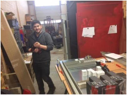
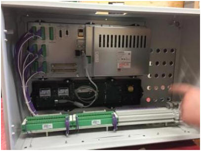
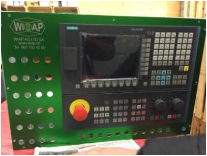
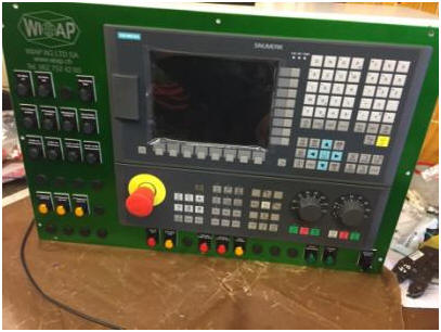
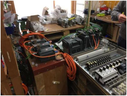
Assembly 31 electrical cabinet and control
Photo 300: Sven in cabinet installation in the electrical department.
Photo 302
Photo 304
Photo 306
Photo 307
Photo 308
Photo 309
Photo 310: The panel with the signs.
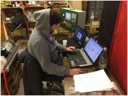
Photo 311: Sven by PLC programming. Change language from English to German, integrate the new axes, etc.
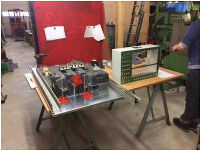
Photo 312: Everything is set up to test that if we mechanically the machine have done everything runs already and is preset.
Very interesting today. In previous years, the WIAP had let others do much externally. Especially electric. Today everything comes from a single source that simplifies much. Once it is recognized that an engine comes to that action can be taken quickly straightforward.
Signs order: - Control voltage OK - Security key - Drives on - Gripper from loading on - Gripper from loading to - Gripper of loading lift - Gripper of loading low - Workpiece stop before - Workpiece stop back - Vib. engine on - Vib. engine off - RT rotary claw forward - FT rotary claw back - FT carriage position forward - FT carriage position center - FT carriage position behind - Fault active - Horn zone front was active - Horn zone back was active - Reset Horn zone - Stamping Start
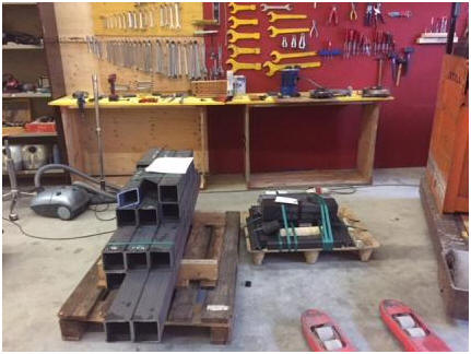
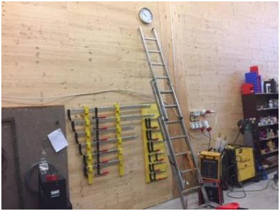
Workshop equipment
Photo 200
Photo 202
Created: sw-jw-iw-hp Widmer
WIAP® AG-Ltd-SA Industriestrasse 48L CH-4657 Dulliken Telefon: ++41 62 752 42 60 Telefax: ++41 62 752 48 61
|
![]()
![]()
![]()
![]()