|
|
Multiple clamping
![]()
|
Introduction
More than one component to relax at the same time with vibration, is a question that often. Above all, the results have been shown to be inadequate in some investigations reports for small parts. The WIAP has chosen a solution where a change in direction of the excitation is not very disturbing. The quality of the transfer materials was also taken into account in order to avoid too great a loss negatively affects the process to the end product. A heavy table with lightweight components is not well controlled.
Photo presentation
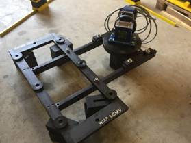
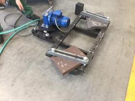
Photo WM838a_1. Multiple clamping device for 6 x 330 mm, or 3 mm x 550 or 1 x 900 mm. System for the hub tension.
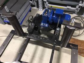
Photo WM838a_2. % Setting 0-15500 N stimulator energy.
Photo WM838a_3. Rotational direction of the stimulator energy.
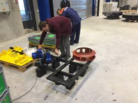
Photo WM838a_4. Single impeller on the multiple clamping.
Photo WM838a_5. dito diameter 1300 mm.
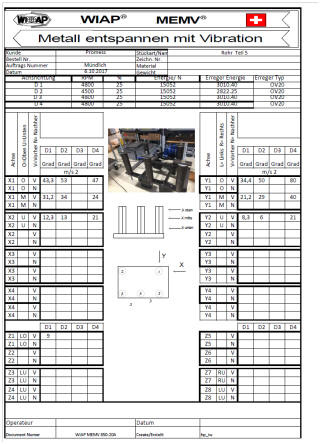
Photo WM838a_6. Status survey of the stimulator axes, which the X = transverse waves, Z = longitudinal waves, Y = transverse or shear waves perpendicular do. It is created with all positions a protocol in addition to the means of the control device.
Photo WM838a_7. The process runs automatically. The speed is regulated themselves. Monitoring, which touches on a risk value automatically down-regulated or triggers even in an emergency stop when the device stimulates the natural resonance value with a high G.
Photo WM838a_8. 3 Impeller diameter 550 mm, diameter on the multiple clamping device.
Photo WM838a_9. All axes are to be stimulated only a relaxation done enough. Which values G (1 G = 9.81 m / s2) at which point, as will be the exact formula WIAP determined.
The multiple clamping device has shown in the measurements that it reaches all areas of all clamped components. The differences from the part 1 to 2 (Dia. 800) or 1 to 3 (up diam. 550) or the item diam. 1300 were almost identical; ie a deviation of about 15% at the impeller variant. The reduction is the same for all parts when no inequality of G value per axis. Which G values for which component type yet to be set, is not yet determined. Whether a large displacement at low speeds and high stimulator is% level, or whether a small deflection with small eccentric stage for high Hertz number you want to dial is in the discovery process. The fully automatic system with automatically adjustable eccentric stage is available as a further variant. As a result, the G shift between before and after are taken per axial direction.
Note:
In general, each vibrating body has several such natural frequencies or vibrational modes. Characteristic of these modes are the type of propagation and the direction of vibration. In solids, a distinction longitudinal and transverse vibration modes. Longitudinal waves vibrate in the direction of propagation, shear waves or transverse or shear waves perpendicular thereto.
We are trying to encourage all directions.
If we take a robust welding table or a cast iron table, then tighten more components on the transfers to the component are less effective than if we choose a lightweight one- multiple clamping device. The exact investigations are still in process and will be announced soon.
Multiple clamping device investigation
5 tubes clamped
Base frame WIAP MEMV 1000x540 without a cover plate
Photo WM838a_10
Photo WM838a_11
Photo WM838a_10
According to the component analysis, the component vibrates up several times, with respect to the bottom of the mounting surface. Although each component we have a tightening screw of M16, that we spin with about 8 tons a component of 20 kg down. Diameter 100 mm; inward about 56 mm; Length 600 mm. The component is in an excitation top and has by its own weight a much greater deflection in the most distant zone from the clamping.
Sketch WM838a_11
Sketch WM838a_11
The analysis shows that we need to make a top frame. The components vibrate up high, down to the binding site much less.
Sketch WM838a_13. Component analysis, 5 logs are created for each component.
The jig for the component will be adjusted.
Multiple clamping end report it is expanded in the course of further investigations SW / JW / IW / HPW
Update April 2019:
Test XY3 to XY8; 5.3.2018 11:30 to 14:00
Part name: BEARING DRAFTING Component Type: 11017702 Component weight: 20 kg Material: GG-25 Number / components: 3 x 2 pcs. Zone displacement X 20.3 m/ s2 Zone offset Y: 17.2 m/ s2 Zone Z displacement: 4.8 m/ s2 Stimulated axis / min: XY 3/4 D5 / D2 15/15' XY5 / 6 D1 / D2 / D4 8/8/8 ' XY7 / 8 D1 / D2 / D3 8/8/8 '
6 pieces molded. C15 Mass: Problem: warp when editing Vibration Relaxed: 1. Clamping 2 x 15 minutes D5 and D3 2. Clamping 3 x 8 minutes D2 and D3 and D1 3. Clamping 3 x 8 minutes D1 and D2 and D3 Here the parts of the first setup were good; the parts of the second and third not.
Figure 10. Measurement test protocol attesting to the Art.
Figure 11: 1st clamping D5
Figure 12. Clamping D1
Figure 13.
|
Figure 14. 2 clamping D3
Figure 16. Clamping D3
Result: XY 3 to XY8: XY 3 and XY4. D5 and D2 relaxed, result OK. XY5, 6, 7, 8 relax not with D1, D2, D3 result ok, see Figure 10. The measuring protocol. Action: Only D5 and D2 MEMV relax and long-term test.
Test XY9 to XY12 5.3.19 14:00 to 15:00
Part name: SUPPORT FRAMEWORK Component Type: H04960742 Component weight: 9 kg Material: Steel S235JRC + C Number / components: 4 pcs Zone Offset X: 65 m/ s2 Zone displacement Y: 67 m/ s2 Zone offset Z: 39.8 m/ s2 Stimulated axis / min: D1 / D2 / D3 8/8/8'
Figure 17.
Figure 18.
Figure 19.
Figure 20.
Result: XY9 to xy12: not confirmed Action: make more tests. For example, middle struts connect so that they do not continue swinging freely. Other frequencies. Make time test.
Test XY17 to 20 6.3.19 08:15 to 09:15
Part name: rail Component Type: pole Component weight: 11 Kg Material: C45E + C Number / components: 4 pcs Zone Offset X: 190 m/ s2 Zone displacement Y: 27 m/ s2 Zone Z displacement: 113 m/ s2 Stimulated axis / min: D1 / D2 / D3 8/8/8' Treat cold drawn bare rods MEMV. Arrears were like without MEMV, the process must be further examined.
Figure 26.
Figure 27. View raw material
Figure 28. Multidirectional MEMV
Result: XY17 to XY20 no change between MEMV and not treated MEMV Mean prevent free-swinging zone with clamping together of all rods: measure. I.e. Packet make voltage. Low frequency, medium frequency and high frequency, and any direction procedures, better vibration test transmission.
Test XY21 to 22 6.3.19 09:15 to 10:15
Part name: feeder bevelled 25/23 SS- Component Type: MPST-10201-001 Component weight: 20kg Material: X6CrNiTi18-10 Number / components: 2 Hours Zone displacement X 61 m/ s2 Zone offset Y: 56.6 m/ s2 Zone displacement Z: 42 m/ s2 Stimulated axis / min: D1 / D2 / D3 8/8/8'
Impellers delay testing with MEMV Clam prisms. Light small parts
Figure 29.
Figure 30.
Figure 31. Clamp prism on multiple clamping
Bild 32.
Result: XY21 to XY22 Action: parts are ok after machining operations – diameter and runout are ok
Result: XY23, 80% of the panel were the parts straight. 20% not ok. Action: are controlled by the software and the machine dead center shift has yet, then all zones are reached.
Test XY24 to XY25 6.3.19 13:15 to 14:00
Part name: UNDER TONG FRONT SWAKT-HC Component Type: H05284082 Component weight: 22 Kg Material: GGG-40 Number / components: 2 Hours Zone Offset X: 117 m/ s2 Zone displacement Y: 40 m/ s2 Zone displacement Z: 13 m/ s2 Inspired axis / min: D2 / D5 15/15 `
Aging test cast plates artificially. Despite MEMV delay was 0.05mm G displacement X = Y = Z = Process D2, D5
Figure 38.
Figure 39.
Result: XY24, XY25 the delay was 0.05mm still testing other axial direction: measure. Better robust setup. increasing maturity
Test XY28 to XY29 6.3.19 15:00 to 16:00
Part name: Lid Rolled component part type. Component weight: 2 kg Material: DD12 Number / components: 2 Hours Zone Offset X: 85 m/ s2 Zone displacement Y: 36 m/ s2 Zone displacement Z: 52 m/ s2 Stimulated axis / min: D1 / D2 15/15'
Sheet metal lid treat MEMV and check whether the delay is to be brought into the part during welding, is smaller. These parts have a strong distortion due to welding. It should be tested when MEMV being treated, the delay is smaller. The presented below is setup should be done with a better ground clamping on the multiple clamping device, which we did not have it. We have to prepare more standard clamping parts for fastening with M24.
Figure 42. Here the process with MEMV plant during the welding operation would be a kind that can reduce 30% or more delay. This would be the device that it is easy to dismantle as an additional variant.
Result: XY28 and XY29 Action:
hpw:iw.sw.jw.cw.
WIAP ® AG Ltd SA Telefon: ++41 62 752 42 60 Telefax: ++41 62 752 48 61 wiap@widmers.info www.widmers.info / www.wiap.ch Industriestrasse 48L CH-4657 Dulliken
|
![]()
![]()
![]()
![]()